
Convincing Features

Assignment Type
Subject
Uploaded by Malaysia Assignment Help
Date
The crank O2A of the four-bar linkage shown in Figure 1 is rotating at a crank velocity of 3 rad/s (clockwise) and the angular acceleration of the crank is 2.5 rad/s2 (counterclockwise).
The dimensions are given as below.
O2A = 100mm, AB = 200mm, O4B = 75mm, AC = 100mm, BC = 150mm, AD= 50mm, and the crank angle as θ2 = 45°. Using the information given, complete the following task:
Using the information given, complete the following task:
(a) Sketch the space diagram of the existing configuration focusing on O2-A-B-O4 linkage length ONLY and estimate the value of coupler AND rocker output angle. [5 Marks]
(b) Use the value from (a) to graphically estimate the linear AND angular velocity of the coupler AND the rocker for the existing configuration. [10 Marks]
(c) Use the value from (a) and (b) to graphically estimate the angular accelerations of the rocker AND the coupler for the existing configuration. [12 Marks]
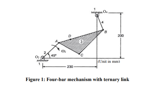
(d) What will happen to the acceleration if a constant input angular velocity is applied instead? Discuss all the possibilities. [3 Marks]
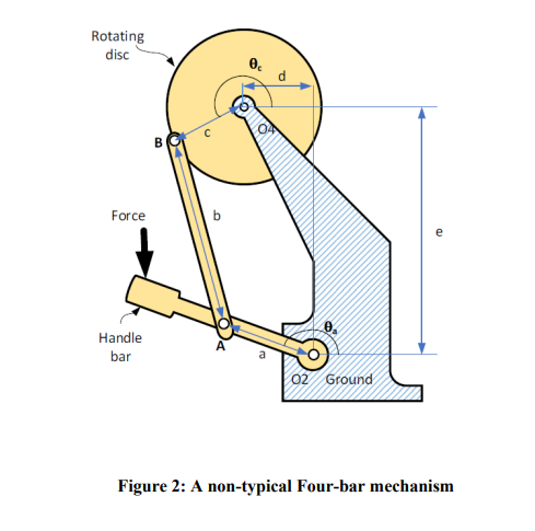
Figure 2 below shows a non-typical four-bar linkage. Link a is the input input, where an external force is applied at the handlebar. The input angle is defined by θa and the handlebar rotates with angular velocity of ωa and angular acceleration of αa. Do the following:
(a) Draw a vector loop diagram for the mechanism. Please ensure that the vector loop diagram is clearly labelled. Please use the given letters and symbols. [3 Marks]
(b) Using the vector loop method, derive equations which are solvable for the velocity of the output variables (w) [4 Marks]
Note: You just need to derive the equations. Please do NOT attempt to solve them.