
Convincing Features

Assignment Type
Subject
Uploaded by Malaysia Assignment Help
Date
Question 1
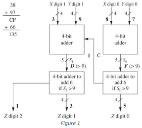
Design a 4-bit BCD adder that will add two BCD numbers and produce the sum in BCD format. If the sum of two numbers is less or equal to 9, then the value of the BCD sum is the same, otherwise, we need to add 6 (01102) to the sum. Figure 2 can be used as a guide. Draw a waveform to ensure the correctness of your design by showing all possibilities required.
Question 2
Design a sequential traffic light controller for the intersection of Jalan_A and Jalan_B. Each street has traffic sensors that detect the presence of vehicles approaching or stopping at intersections.
S_A=1 means a vehicle is approaching Jalan_A.
S_B=1 means a vehicle is approaching Jalan_B.
There are 3 outputs of each street Red_A, Yellow_A and Green_A, Red_B, Yellow_B, and Green_B.
Condition: “Jalan_A” is a main street and has a green light for at least 50s, after 50s if there is a car approaches “Jalan_B”, the light changes to yellow and then red, and “Jalan_B” has a green light for 50s.
At the end of the 50s, the light changed back unless there is a car on “Jalan_B” and none on “Jalan_A”. Start your design with FSM with all possibilities.
Write the Verilog code and waveform of your design.
Question 3
Design a simple Scoreboard which can display scores from 0 to 99. The input of the system should consist of a reset signal and control signals to increment or decrement the score.
The condition:
Question 4
Design a 4-bit array multiplier using combinational logic as shown in figure 1.
Develop a waveform to show that your design is correct by adding all the possibilities.
Download your program into FPGA, and set your input as switch and output in LED seven segment.

Question 5
Develop a synchronous 3-bit up/down counter with Gray Code sequence using D- flip flop. The counter should count up when an 𝑈𝑃/𝐷𝑂𝑊𝑁 ̅̅̅̅̅̅̅̅̅ control input is 1 and count down when the control input is 0. Simulate its waveform to ensure the correctness of your design by showing all possibilities required.
Question 6
Use the RTL design process to create an alarm system that sets a single-bit output alarm to 1 when the average temperature of four consecutive samples meets or exceeds a user-defined threshold value. A 32-bit unsigned input CT indicates the current temperature, and a 32-bit unsigned input WT indicates the warning threshold. Samples should be taken every 5 clock cycles. A single-bit input clr when 1 disables the alarm and the sampling process. Start by capturing the desired system behavior as an HLSM, and then convert it to a controller/datapath. Write your Verilog code and download your program into FPGA. Set LED as your alarm indicator.
Are you looking for case study assignment help? Malaysiaassignmenthelp.com is the place for you! Our reliable and friendly assignment writing experts offer high-quality case study writing and editing services so that you can achieve better results in your academic career. Make sure to tap into all the advantages we have to offer by visiting us today!