

Convincing Features

Assignment Type
Subject
Uploaded by Malaysia Assignment Help
Date
Objective:
To characterize multiple resistive networks by its Thévenin’s equivalent circuit.
Learning Outcome:
Ability to obtain and analyze the Thevenin equivalent circuit.
Theory:
Thévenin’s Theorem: It is a process by which a complex circuit is reduced to an equivalent series circuit consisting of a single voltage source (VTH), a series resistance (RTH), and a load resistance (RL). After creating the Thévenin Equivalent Circuit, the load voltage VL or the load current IL may be easily determined.
One of the main uses of Thévenin’s theorem is the replacement of a large part of a circuit, often a complicated and uninteresting part, with a very simple equivalent. The new simpler circuit enables us to make rapid calculations of the voltage, current, and power that the original circuit can deliver to a load. It also helps us to choose the best value of this load resistance for maximum power transfer.
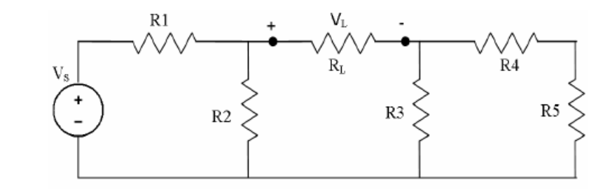
Figure 7.1
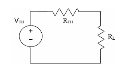
Figure 7.2
Maximum Power Transfer Theorem states that an independent voltage source in series with a resistance RS or an independent current source in parallel with a resistance RS delivers maximum power to that load resistance RL for which RL = RS.
In terms of a Thévenin Equivalent Circuit, maximum power is delivered to the load resistance RL when RL is equal to the Thévenin equivalent resistance RTH of the circuit.
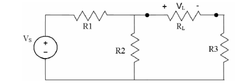
Figure 7.3
Task 1: Verifying Thévenin’s theorem
R1 = 300 W
R2 = 560 W
R3 = 560 W
R4 = 300 W
R5 = 820 W
RL = 1.2 kW
VS = 10 V
VS = 10 V
R1 = R2 = 560 W
R3 = 820 W
RL = Variable Resistor (0-2kW)
Connect the Voltmeter across RL for measuring the load voltage (VL) and Ammeter through RL for measuring load current (IL). Vary the resistance between 600 W to 1.6 kW and note down VL and IL for each case.
Hire university assignment help to complete your electronic assignment. Malaysia Assignment Help has a team of professional writers who offer detailed and 100% plagiarism-free solutions on engineering assignments at a cheap price.